INDIAN ARMED FORCES CHIEFS ON OUR RELENTLESS AND FOCUSED PUBLISHING EFFORTS

The insightful articles, inspiring narrations and analytical perspectives presented by the Editorial Team, establish an alluring connect with the reader. My compliments and best wishes to SP Guide Publications.

"Over the past 60 years, the growth of SP Guide Publications has mirrored the rising stature of Indian Navy. Its well-researched and informative magazines on Defence and Aerospace sector have served to shape an educated opinion of our military personnel, policy makers and the public alike. I wish SP's Publication team continued success, fair winds and following seas in all future endeavour!"

Since, its inception in 1964, SP Guide Publications has consistently demonstrated commitment to high-quality journalism in the aerospace and defence sectors, earning a well-deserved reputation as Asia's largest media house in this domain. I wish SP Guide Publications continued success in its pursuit of excellence.
Technology - The Wonder Radar

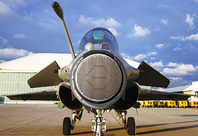
Built on a modular philosophy, AESA radars can receive upgrades to remain updated with the latest available technologies
In the days of yore, dish antennas of fighter radars were mechanically steered concave reflectors. To generate a desired beam pattern, they had to be fabricated to a very high degree of mechanical accuracy. Transmitters had to be fed high voltage power supplies to generate the necessary amount of microwave energy. In addition to presenting large radar signature, the design also tended to produce undesirable large side-lobes.
The breakthrough occurred with the advent of electronic steering. Each of the several planar array elements of the antenna now had an electronically controlled device which could manipulate delay in time or phase of the microwave signal passing through it. Systems using signal phase as the controlling parameter came to be known as ‘phased array radars’.
The antennae of these radars were still passive beam shaping devices while the source of microwave energy required for driving resided elsewhere. Thus they acquired the nomenclature ‘passive phased array’ or ‘passive electronically steered array’ (PESA) radars. Electronic beam steering in this design provided unparalleled beam agility, which in turn made it possible to incorporate concurrent operation of diverse operational modes on a time share basis. However, while innovation of antenna design enhanced overall radar capability by an order of magnitude, certain limitations remained unchanged. Transmitters continued to be saddled with problems associated with high power travelling wave tubes (TWT).
The answer to more and more powerful TWTs lay in embedding several smaller, low powered trans-receivers in the antenna itself, centrally controlled by a command computer to produce the desired beam pattern. However, cost, density and power handling issues remained to be resolved. With passage of time, a host of new devices of mass consumption discovered the virtues of the same chip and the active electronically scanned array (AESA) radars were evolved.
AESA radar
An AESA radar essentially consists of several antenna elements each having its own transmit receive (TR) module, complete with a power amplifier and digitally controlled phase delay/gain elements. Consequently, rather than power supply for the radar’s microwave energy being concentrated in a single high voltage source, in an AESA design, power is distributed amongst hundreds or even thousands of TR modules. Each TR module in an AESA antenna is therefore required to handle much lesser power (of the order of tens of Watts only) fed from relatively low voltage supplies. The design thus side steps all problems associated with high voltage, high power systems.
Digital control over functioning of all TR modules under the authority of a command computer makes it possible to shape the beam precisely as also make it extremely agile. These capabilities combined with extremely high scan rates achievable with electronic scanning yield a number of unprecedented capabilities. Thus AESA radars are distinguished by their ability to undertake multiple tasks simultaneously. By interleaving the highly agile beam in near real time, APG-79 fielded on US Navy’s F/A-18E/F Super Hornet can operate simultaneously in air-to-air and air-toground modes. A unique resource manager, it automatically schedules tasks to optimise radar functions and minimise the workload of the air crew. The radar can thus continue scanning while communicating with other aircraft and capturing ground imagery and can simultaneously guide multiple weapons to multiple targets widely spaced in azimuth, elevation and range.
Compared to a concave dish antenna of conventional radar, a flat phased array offers a much smaller radar cross-section signature when illuminated. Digital control enables precise beam shaping, control over TR module gain, power management, and very significant reduction of side-lobes. Radar warning receivers (RWRs) typically work by integrating received signals over a short period to identify a threat over random background noise. Frequency and PRF of detected pulses is compared against a threat library to identify the type of threat. AESA radars can change frequency with every pulse and generally do so using pseudo-random sequence. Thus integration process over a short period of time doesn’t help to pull the signal out of background noise. PRF also being randomly variable helps conceal the radar’s identify. Thus AESA design makes for a low probability of intercept.
Digital control also enables an AESA to change its operating frequency across a wide band with every pulse and even within a pulse. This attribute makes a jammer’s task much more difficult. Jammers could employ broadband white noise in an effort to swamp all possible frequencies. But the effectiveness of such a technique is vastly degraded. AESA could in the event switch to ‘receive only’ mode and use the powerful jamming signal to track the source for counterattack.
In addition to performing diverse radar functions simultaneously viz. searching volumes of airspace for aerial targets, designation of multiple targets for air-to-air missile engagements, ground mapping, etc, AESA radars can also be employed for non-traditional ISR, as well as electronic attack. For example, some of the elements could be designated to transmit and receive signals modulated with a data link waveform. By combining with state-of-the-art high-speed data links, Raytheon has demonstrated that an AESA radar can serve as a highly advanced communication node capable of such tasks as transmitting large amounts of data (like a SAR map of a target or other battlefield intelligence) with unprecedented speed—while continuing to perform full range of traditional radar functions. Raptor F-22’s AESA radar has demonstrated data transmission at 548 mbps and reception of signals at gigabit speed. To put it in perspective, Link 16 system transfers data at just over 1 mbps.
Active arrays of AESA radar can be put to other functions too. Since each of the TR elements is a powerful radio receiver on its own right, several of them could be dedicated to reception of radio signals to substitute for a separate RWR.
In addition to the tremendous versatility, AESA radar’s design offers several other advantages. Transmitter power being distributed across a large number of modules implies that failure of a few modules may lead only to marginal degradation of performance rather than total loss of antenna function. This feature enables accommodation of some failures until the radar can be taken down for scheduled servicing. The cumulative benefit of AESA design features means that the antenna may have to be removed for repair/servicing once in a few years only, rather than the typical every few hundred or even lower hours of operations.
Limitations
As always, there is a cost attached to high performance. AESA modules dissipate a lot of heat which must be extracted efficiently to maintain reliability of GaAs MMIC chips. High packaging density of the modules precludes the possibility of air-cooling techniques traditionally used in avionic hardware. Thus relatively more elaborate liquid cooling methods involving pumps to drive the coolant through channels in the antenna, heat exchangers, etc have to be adopted. Therefore, in comparison to a conventional aircooled fighter radar, while AESA delivers far greater performance and is much more versatile, it requires more electrical power and more complex cooling systems.
Compared to conventional radars, an AESA also relies much more heavily on enormous amounts of data and the integrity of its processing. It is a software intensive system which could conceal vulnerabilities of interference.


